|
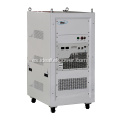
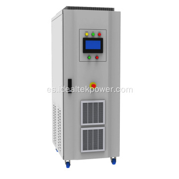
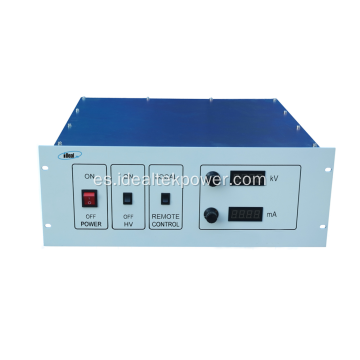
Front panel
description
|

|
|
No.
|
Name
|
Function
|
Operation / display instruction
|
|
F1
|
Control cabinet air inlet
|
Control cabinet heat dissipation air inlet
|
Keep it clean and smooth
|
|
F2
|
Handle
|
For
moving and lifting purpose
|
|
|
F3
|
Mounting hole
|
For cabinet installing and fixing
|
|
|
F4
|
POWER
switch
|
Supply
electric ON/OFF switch
|
Switch to ON position è Power ON
Switch
to OFF position è Power OFF
|
|
F5
|
VOLTAGE
|
Output voltage real-time display
|
Digital LED display
|
|
F6
|
CURRENT
|
Output
current real-time display
|
Digital
LED display
|
|
F7
|
Indicator lights
|
Real-time indication of module working state
|
Indicator lights display
|
|
F8
|
Voltage
Adj.
|
Output
voltage adjusting
|
Turn
as icon, clockwise adjusting for increasing output voltage, anticlockwise
adjusting for decreasing output voltage.
|
|
F9
|
Current Adj.
|
Output current adjusting
|
Turn as icon, clockwise adjusting for increasing output current,
anticlockwise adjusting for decreasing output current.
|
|
F10
|
Analog
port
|
232/485
optional port (N/A for this unit)
|
Please
connect to DB9 port for communication with host.
|
|
F11
|
Start/Stop (with lock)
|
HV output start/stop
|
Press down (green light ON) è HV START
Press
up (green light OFF) è HV STOP
|
|
F12
|
Charging/Charged
|
Charging
/ Charged state indicator light
|
Charging
lighted è Under charging.
Charged lighted è Charging finished.
|
|
Front Panel Indicator Lights Description
|

|
|
No.
|
Name
|
Function
|
Operation
/ display instruction
|
|
F13
|
Host indicator light
|
Green LED light, lighted when power supply
works as host unit under multi-unit parallel-working.
Note: host indicator light lighted under
single-unit working.
|
Indicator lights display
|
|
F14
|
Slave indicator light
|
Green LED light, lighted when power
supply works as slave unit under multi-unit parallel-working.
Note: slave indicator light not lighted
under single-unit working.
|
Indicator lights display
|
|
F15
|
C.V. indicator light
|
Green LED light, lighted when power supply
works under CV state.
|
Indicator lights display
|
|
F16
|
C.C. indicator light
|
Green LED light, lighted when power
supply works under CC state.
|
Indicator lights display
|
|
F17
|
Flashover indicator light
|
Red LED light, lighted when power supply
output has disruptive discharging.
|
Indicator lights display
|
|
F18
|
OC indicator light
|
Red LED light, lighted when power supply
has internal inverter output over current.
|
Indicator lights display
|
|
F19
|
Out short indicator light
|
Red LED light, lighted when power supply has
output short-circuits.
|
Indicator lights display
|
|
F20
|
OP indicator light
|
Red LED light, lighted when output power
of high voltage power supply exceeds the limit.
|
Indicator lights display
|
|
F21
|
Inhibit indicator light
|
Red LED light, lighted when power output is
prohibited by client's external nodes.
|
Indicator lights display
|
|
F22
|
OT indicator light
|
Red LED light, lighted when power supply
has internal module over temperature.
|
Indicator lights display
|
|
F23
|
Grid indicator light
|
Red LED light, lighted when power supply has
input abnormal (i.e.: lack phase or out of scope)
|
Indicator lights display
|
|
F24
|
IGBT indicator light
|
Red LED light, lighted when power supply
has internal inverter fault
|
Indicator lights display
|
|
F25
|
OV indicator light
|
Red LED light, lighted when output voltage
goes out of scope.
|
Indicator lights display
|
|
F26
|
Load OC
indicator light
|
Red LED light, lighted when output
current goes out of scope.
|
Indicator lights display
|
|
F27
|
APS indicator light
|
Red LED light, lighted when internal
auxiliary power supply is working.
|
Indicator lights display
|
|
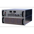
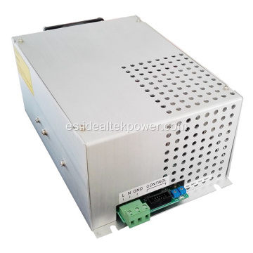
Back panel description
|

|
|
No.
|
Name
|
Function
|
Operation / display
instruction
|
|
B1
|
GND
|
Main
circuit part, connected to earth.
|
Separately
connected to earth.
|
|
B2
|
HV cabinet (Feedback) air socket
|
For connection of HV cabinet and control cabinet.
|
Connect to control cabinet (Feedback) air plug
|
|
B3
|
Control
cabinet (H-power) air socket
|
For
connection of control cabinet and HV cabinet.
|
Connect
to HV cabinet (H-power) air plug
|
|
B4
|
Control cabinet input port
|
Remote 485 signal input port
|
Leave it unconnected if no 485 signal used.
|
|
B5
|
Control
cabinet DB9 port
|
Remote
control / reading port
|
Connect
in external analog signal for remote control / reading (i.e.: 0~10V)
|
|
B6
|
Control cabinet DB15 port
|
Remote start/stop, fault state TTL signal port
|
Connect in external start/stop signal
(i.e.: 24V)
Connect in external analog signal for fault state indication
(i.e.: TTL signal)
|
|
B7
|
Control
cabinet (Feedback) air socket
|
For
connection of control cabinet and HV cabinet
|
Connect
to HV cabinet (Feedback) air plug
|
|
B8
|
Cooling fan (temperature-controlled)
|
Exhaust fan, controlled by temperature inside the cabinet
|
The higher the temperature inside cabinet, the faster the fan
speed is.
|
|
B9
|
IN
480V~600VDC
|
Connects
to DC480V~600V input
|
Red
is positive, black is negative.
|
|
B10/11
|
HV-output
|
Negative HV output connector
|
Connection port
|
|
B12
|
Power
GND
|
Positive
output connector
|
Connection
port
|
|
B13
|
HV cabinet (H-power) air socket
|
For connection of HV cabinet and control cabinet.
|
Connect to control cabinet (H-power) air plug
|
|
Remote interface definition
|
|

|
|
B4 Wiring diagram / B5
Internal wiring / B6 Wiring diagram
|
|
No.
|
Name
|
Function
|
Operation / display
instruction
|
|
Z-1
|
485-A
|
485-A
|
485-A
|
|
Z-2
|
485-B
|
485-B
|
485-B
|
|
Z-3
|
Remote ON/OFF state node
(optional)
(N/A for this unit)
|
ON/OFF
state node +
|
Power OFF, node closed
Power
ON, node open
|
|
Z-4
|
|
ON/OFF state node -
|
|
|
X1
|
Voltage
remote control (optional) (N/A for this unit)
|
Voltage
remote control +
|
0-10V
signal for 0-15KV output voltage setting
|
|
X2
|
|
Voltage remote control -
|
|
|
X3
|
Current
remote control (optional) (N/A for this unit)
|
Current
remote control +
|
0-10V
signal for 0-1000mA output current setting
|
|
X4
|